
Arc Flash Study
Arc flash studies to quantify incident energy, define safe working distances, and provide labels, PPE guidance, and documentation that align with NFPA 70E and IEEE 1584-2018. PE-led, for facilities across the San Francisco Bay Area and Northern California.
Arc flashes are low-probability but high-consequence events. A proper study helps you understand where the risk exists, how severe it can be, and what protection and work practices are required so people go home safe after every shift.
What Is An Arc Flash And Why It Matters
An arc flash is a rapid release of energy caused by an electrical fault through air, often accompanied by an arc blast. In a fraction of a second, temperatures can reach tens of thousands of degrees, generating intense radiant heat, molten metal, high sound levels, and pressure waves. The heat can ignite clothing well beyond arm’s reach, and the pressure wave can move a person across a room.
For workers standing in front of a piece of equipment, the questions are:
- How much incident energy will reach the worker at a realistic working distance?
- What level of PPE is required to work safely on or near that equipment?
- Are there settings or equipment changes that can reduce that energy?
Arc flash hazard analysis answers those questions in a systematic, documented way. The output is not an opinion about risk; it is a calculated number at each piece of equipment, with the assumptions behind it written down.
When An Arc Flash Study Is Required Or Recommended
Typical triggers for a full or updated analysis:
- New construction or major service upgrades
- Replacement of switchgear, switchboards, MCCs, or large panelboards
- Addition or replacement of transformers, generators, or large motors
- Reconfiguration of feeders and distribution sections
- The last study is older than five years
- Changes to codes or corporate safety standards that require updated labeling and PPE guidance
- A prior study built on the 2002 edition of IEEE 1584, which used a different calculation model
- Utility service changes, which move available fault current and therefore move incident energy
Our Process
1. Listen and define the scope
We review your goals, existing drawings, and any prior studies, then define which buildings, rooms, and equipment will be modeled and labeled.
2. Collect data and build the model
We gather equipment information from drawings and field visits, then build or update a detailed power system model with fault current, clearing times, and system impedance.
3. Perform arc flash calculations
Using IEEE 1584-2018 methods, we calculate incident energy and arc flash boundaries at each location within the study scope.
4. Evaluate results and recommend improvements
We review high-energy locations, evaluate possible setting changes or equipment options, and discuss trade-offs with your team.
5. Documentation, labels, and review
We prepare the written report, schedules, updated one-lines, and label files, and meet with your team to walk through the results and next steps.
How Incident Energy Is Calculated
Incident energy is the thermal energy that would reach a surface at a given distance from an arc, expressed in calories per square centimeter (cal/cm2). It is what determines the arc flash boundary and the required PPE rating. IEEE 1584-2018 replaced the 2002 model that most older studies were built on, and the two do not produce the same answers.
What the 2018 model needs that the old one did not
- Electrode configuration – five arrangements, each with its own equations: VCB (vertical conductors in a box), VCBB (vertical conductors in a box terminating in an insulating barrier), HCB (horizontal conductors in a box), VOA (vertical conductors in open air), and HOA (horizontal conductors in open air)
- Enclosure dimensions – height, width, and depth feed a correction factor that can materially change the result
- Arcing current variation – the calculation is run at both the predicted arcing current and a reduced value, because a lower arcing current can mean a slower trip and therefore more energy
- Working distance – the distance from the arc to the worker’s face and chest, which is an input, not a constant
Where the model is valid
- Voltage from 208 V to 15 kV, three-phase AC
- Bolted fault current from 500 A to 106,000 A at 208 to 600 V, and from 200 A to 65,000 A above 600 V
- Conductor gap of 0.25 to 3.0 inches at 600 V and below, and 0.75 to 10 inches above 600 V
- Above 15 kV the standard does not apply, and other methods, most commonly the Lee method, are used instead
- Below 208 V the standard offers no validated model, which is a limitation to state rather than a reason to skip the equipment
These parameters are why a walk-down matters. Electrode configuration and enclosure size cannot be read off a one-line diagram, and a study that assumes defaults for both is reporting a number it has not really calculated. Where we have to assume, we say so in the report.
What The Label Must Say
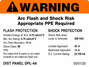
CEC 110.16(A) – general arc flash warning
Equipment in other than dwelling units that is likely to require examination, adjustment, servicing, or maintenance while energized must be field or factory marked to warn qualified persons of potential arc flash hazards.
CEC 110.16(B) – service equipment rated 1000 A or more
In other than dwelling units, service equipment and feeder-supplied equipment rated 1000 A or more must carry a permanent arc flash label that follows applicable industry practice and shows the date it was applied. Under NFPA 70E, that label carries:
- Nominal system voltage
- The arc flash boundary
- Incident energy and working distance, or PPE category, or minimum arc rating of clothing, or site-specific PPE
- The date the label was applied
The 2025 California Electrical Code adopted these 2023 NEC changes: the threshold dropped from 1200 A to 1000 A and now includes feeder-supplied equipment. A label carrying incident energy, arc flash boundary, working distance, and required PPE serves both the electrician who has to work on the gear and the inspector who has to sign it off.
What We Deliver
A typical arc flash hazard analysis from Apex Arc Flash Engineering includes:
- Arc flash model and calculations based on IEEE 1584-2018 methods
- Incident energy and arc flash boundary at each studied bus or equipment location
- Arc flash labels in a consistent layout, ready for printing and installation
- One-line diagrams that match the model and field conditions
- Summary tables for management and safety teams
- Recommended protective device settings where adjustments can reduce incident energy without compromising coordination
- A clear narrative explaining methods, assumptions, and limitations of the study
What We Need From You
To scope and execute an arc flash hazard analysis efficiently, we typically request:
- Existing one-line diagrams and panel schedules, if available
- Service and transformer information (utility short-circuit data when possible)
- Access for field verification and equipment nameplate photos
- Any previous studies or protective settings documents
- Site safety rules for escorting and PPE during field work
- Badging, clearance, or escort lead times, which are often the longest item on hospital and data center projects
Reducing Incident Energy
A study that only reports hazards is half the job. Incident energy rises with clearing time, so most practical mitigation comes down to making the upstream device operate sooner, without giving up the coordination that keeps the rest of the facility running:
- Protective device setting changes, which cost nothing but engineering time and are always evaluated first
- Maintenance switches, which lower the trip setting while someone is working and restore it afterward
- Zone-selective interlocking, which lets devices communicate so the closest one trips fast
- Arc energy reduction per CEC 240.87, required on newly installed circuit breakers rated or adjustable to 1200 A or more, and available as voluntary mitigation on existing gear
- Differential protection on larger services and switchgear
- Remote racking and remote operation, which move the worker outside the boundary instead of lowering the energy
- Arc-resistant switchgear where equipment is being replaced anyway
Every option here trades against something else, usually selectivity or capital cost. We plot the effect of each one rather than recommending hardware by default.
Codes And Standards
Our arc flash work is driven by current industry standards and codes, including:
NFPA 70E:
NFPA 70E 130.5 requires that an arc flash risk assessment be performed to determine whether an arc flash hazard exists and, if it does, to determine the safety-related work practices, the arc flash boundary, and the PPE to be used within that boundary. It further requires the assessment to be updated when a major modification or renovation takes place, and reviewed at intervals not exceeding five years.
California Electrical Code (CEC)
- 110.16(A) – arc flash warning marking on equipment likely to be examined or serviced while energized, other than dwelling units
- 110.16(B) – permanent arc flash labels on service and feeder-supplied equipment rated 1000 A or more, including the date applied
- 110.24 – service equipment field marked with maximum available fault current and calculation date, updated when modifications change it
- 110.9 and 110.10 – interrupting rating and circuit impedance, which govern the short circuit work the arc flash model is built on
- 240.87 – arc energy reduction on newly installed circuit breakers rated or adjustable to 1200 A or more
OSHA and IEEE
- 29 CFR 1910.132(d) – workplace hazard assessment, PPE selection, and written certification identifying the workplace, the person certifying, and the date
- 29 CFR 1910.335(a)(1)(i) – employees in areas with potential electrical hazards must be provided with and use appropriate electrical protective equipment
- 29 CFR 1910.269(l)(8) – arc hazard assessment and incident heat energy estimate, applicable to electric power generation, transmission, and distribution work
- IEEE 1584-2018 – the calculation method for arcing current, incident energy, and arc flash boundary
- IEEE 3002.3 – short circuit studies, which supply the fault current the arc flash model runs on
Code references are to the California Electrical Code as adopted in Title 24, Part 3. OSHA sets what must be done; NFPA 70E describes how. Requirements vary by code edition and by the authority having jurisdiction. We align our deliverables with your internal safety programs and any corporate EHS requirements.
Healthcare And HCAI
Hospital projects in California are reviewed by the Department of Health Care Access and Information (HCAI), formerly OSHPD. Arc flash work on these projects sits downstream of two other studies, and the submittal is usually evaluated as a set rather than a single document.
- The short circuit study establishes available fault current at each location
- The coordination study, governed by HCAI PIN 70, Electrical Coordination, establishes clearing times
- Those clearing times drive the incident energy result, so coordination decisions and arc flash results cannot be developed independently
- CEC 517.31(G) requires coordination for faults extending beyond 0.1 second, a narrower requirement than full selective coordination
Essential electrical system equipment, generator paralleling gear, and transfer switch enclosures are where incident energy most often surprises facilities staff. Reference: HCAI PIN 70, Electrical Coordination.
FAQs
Q: Do you need to shut down power to perform the study?
Usually not. Most data comes from drawings, nameplates, and visual inspection while equipment stays in normal operation. If covers must be removed, we coordinate an outage and follow your lockout/tagout procedures. We do not perform energized work unless it is absolutely necessary and agreed in advance.
Q: How often does the study need to be updated?
An arc flash study must be updated whenever changes occur in the electrical distribution system that could affect the results of the analysis, and it should be reviewed for accuracy at intervals not exceeding five years.
Q: Can you work from our existing model or study?
Yes. We can review previous work, update data where needed, and bring the study in line with current standards and your present system configuration.
Q: What is incident energy, and what does cal/cm2 mean?
Incident energy is the thermal energy that would reach a surface at a given distance from an arc, measured in calories per square centimeter. Roughly 1.2 cal/cm2 is the threshold commonly associated with the onset of a second-degree burn on bare skin, which is why PPE is rated in the same units and must meet or exceed the calculated value at the working distance.
Q: What is the arc flash boundary, and how is it different from the working distance?
The arc flash boundary is the distance from exposed energized parts at which incident energy falls to the second-degree burn threshold. The working distance is where the worker’s face and chest actually are during the task, typically 18 inches at low-voltage panelboards and motor control centers and 24 inches at low-voltage switchgear. Incident energy is calculated at the working distance; the boundary is calculated outward from the arc.
Q: Do 208-volt panels need arc flash labels?
Generally, yes. IEEE 1584-2018 covers 208 V and above, so 208 V equipment is modeled rather than assumed safe. Sustaining an arc at 208 V is harder and the calculated energy is often low, but NFPA 70E’s assessment requirement has no voltage floor, and CEC 110.16(A) labeling applies to equipment likely to be serviced while energized regardless of voltage.
Q: Which edition of IEEE 1584 do you use, and does it matter?
We use IEEE 1584-2018. It matters. The 2018 edition replaced the 2002 model and added electrode configuration and enclosure dimensions as inputs, so the same equipment can produce a different incident energy result under the two methods. If your current labels came from a study built on the 2002 model, the numbers on them were calculated a different way.
Q: Can an arc flash study lower our PPE requirements?
Sometimes, and that is a legitimate goal rather than a corner being cut. Incident energy depends heavily on how fast the upstream device clears, so a setting change, a maintenance switch, or zone-selective interlocking can move equipment into a lower PPE category. What we will not do is reach a lower number by assuming a shorter clearing time than the device will actually deliver.
Q: Do you work on hospital projects under HCAI review?
Yes. We prepare short circuit, coordination, and arc flash studies to support HCAI submittals, including the coordination requirements of PIN 70. Because clearing times drive incident energy, we develop the coordination study and the arc flash results together rather than in sequence.
Q: How long does an arc flash study take?
It depends on the number of buses, the quality of existing documentation, how quickly the utility returns fault current data, and site access for field work. The utility request and site badging are usually the longest lead items. We give a realistic schedule in the proposal rather than a default number.
Who provides arc flash studies in the San Francisco Bay Area?
Apex Arc Flash Engineering provides PE-led arc flash hazard analysis, short-circuit studies, protective device coordination studies, and single-line diagram development for electrical contractors, manufacturers, hospitals, laboratories, schools, universities, commercial facilities, and public agencies throughout the San Francisco Bay Area and California.