
Single Line Diagram Development
Creation or cleanup of single line diagrams so your documentation matches the field and supports accurate studies and maintenance. PE-led, for facilities across the San Francisco Bay Area and Northern California.
Accurate one-line diagrams are the foundation for any meaningful power system study. Without them, it is difficult to manage risk, plan projects, or respond to problems. A drawing that disagrees with the field is worse than no drawing at all, because people trust it.
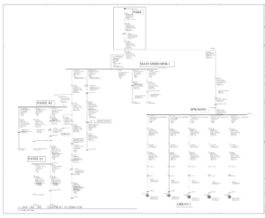
Why Single Line Diagrams Matter
A single line diagram (SLD), also called a one-line, is the map of your electrical distribution system. It shows:
- Sources (utility, generators)
- Transformers and major distribution equipment
- Feeders, bus ducts, and major branch circuits
- Breakers, fuses, and protective devices
If the diagram is outdated, incomplete, or spread across multiple drawings, it becomes hard to:
- Plan maintenance or switch operations
- Perform short circuit, coordination, or arc flash studies
- Evaluate the impact of new projects
- Train new staff or contractors
- Answer a utility, inspector, or plan checker without a scramble
When You Need New Or Updated SLDs
- No existing one-line diagrams, or only partial sketches
- Drawings are decades old and do not reflect current conditions
- Significant projects have been completed without as-builts
- Multiple consulting teams and contractors have made changes over time
- A study is planned, and modeling cannot start without a reliable one-line
- Drawings exist only as scanned PDFs or paper, with no editable source file
- Equipment names on the drawing no longer match the labels in the field
Our Process
- Review existing drawings and records
- Conduct field verification and equipment walkdowns as needed
- Build or update the single line in CAD or your preferred format
- Coordinate equipment naming and references with your team
- Issue draft diagrams for review and comment
- Document discrepancies between the drawings and the field
- Issue draft diagrams for review and comment
What Belongs On A Single Line Diagram
A one-line that shows only boxes and lines is a picture. A one-line that can carry a short circuit, coordination, or arc flash model has to carry data. Where the diagram is intended to support studies, we capture:
Sources
- Utility service transformer kVA, impedance, primary and secondary voltage, and connection
- Available fault current and X/R at the service point
- Generator kW or kVA, voltage, subtransient reactance, and grounding arrangement
- System grounding at each voltage level: solidly grounded, resistance grounded, or ungrounded
Distribution
- Transformer kVA, voltages, impedance, connection, and tap setting
- Conductor size, quantity per phase, material, insulation, and approximate length
- Bus ampacity and bracing or withstand rating
- Normally open and normally closed tie points, and the switching configuration they represent
Protective devices
- Manufacturer, type, and frame size
- Trip unit type, sensor and plug rating, and as-found settings
- Interrupting rating, and the assembly short-circuit current rating where it governs
- Fuse class and rating where fuses are used
Conductor lengths and as-found breaker settings are the two items most often missing, and both go straight into the incident energy result. We capture them during the walkdown rather than assuming them later.
What We Deliver
- Clean, standardized single line diagrams in PDF and CAD formats
- Clear device naming conventions and equipment identifiers that match field labels
- Voltage levels, ratings, and key settings annotated where appropriate
- Logical sheet organization by building, floor, or distribution level
- Consistent, industry-standard symbology throughout
- A written list of discrepancies found between existing drawings and field conditions
- Editable source files, so the drawing stays yours to maintain
What We Need From You
- Any existing drawings, sketches, or panel schedules
- Access to electrical rooms and roof or yard equipment
- Preferred naming conventions or CAD standards, if applicable
- Badging, escort, or clearance requirements, identified early
- A point of contact who knows the recent project history, which is often more useful than the drawings
Who Performs The Work
Single line diagram development at Apex is performed under the direction of a California licensed Professional Engineer (PE) in Electrical Power Engineering with more than decades of experience on healthcare, institutional, commercial, and industrial power systems.
As-Found Versus As-Built
As-built drawings record what the design intended at the time of construction. As-found records what the field survey actually shows. On a facility older than a few years, these are rarely the same document.
What field verification typically turns up:
- A breaker replaced with a different frame, trip unit, or interrupting rating
- A tie breaker in the opposite position from what the drawing shows
- A panel re-fed from a different source during a renovation, with no drawing change
- Circuits marked spare that are energized, and energized circuits marked spare
- Conductor quantity per phase changed during a capacity upgrade
- Equipment renamed in the field but not on the drawing, or the reverse
We record both and flag the differences rather than quietly adopting one version. A discrepancy is a finding, not an embarrassment, and it is usually cheaper to resolve on paper than during an outage.
Codes And Standards
NFPA 70E 205.2
“A single-line diagram, where provided for the electrical system, shall be maintained in a legible condition and shall be kept current.” Note the conditional. 70E does not by itself require you to create a one-line; it requires that the one you have be legible and current.
NFPA 70B
Since its 2023 edition, NFPA 70B has been the Standard for Electrical Equipment Maintenance, converting its guidance from “should” to “shall.” It calls for single line diagrams to be kept accurate and legible, and for short circuit studies, coordination studies, and incident energy analyses to be reviewed for accuracy every five years and updated when system changes could affect the results.
NFPA 70B is not automatically law. It becomes binding through adoption by a jurisdiction, a contract requirement, an insurer’s conditions, or as evidence of recognized hazard and feasible abatement under the OSHA General Duty Clause. We mention it because it is increasingly written into specifications and insurance requirements, not because it is a citation waiting to happen.
Where the one-line is a required deliverable
- CEC 110.24 – service equipment field marked with maximum available fault current and calculation date, which depends on the system data the one-line carries
- CSI MasterFormat Section 26 05 73, Power System Studies, which commonly lists an updated one-line among the required submittals
- HCAI submittals for California healthcare projects, where the one-line accompanies the short circuit and coordination studies
- OSHA 29 CFR 1910.132(d) – the hazard assessment that cannot be performed without knowing how the system is actually connected
Code references are to the California Electrical Code as adopted in Title 24, Part 3. Requirements vary by code edition, by the authority having jurisdiction, and by what your own specifications and insurer require.
FAQs
Q: Can you work in our CAD template?
Yes. We can adapt to your title blocks, layers, and symbols or provide a clean standard if you prefer.
Q: Will the diagrams be usable for future studies?
Yes. We draw SLDs with enough detail and structure to support short circuit, coordination, and arc flash modeling.
Q: What is a single line diagram?
A single line diagram, or one-line, is a simplified drawing that represents a three-phase electrical distribution system using a single line for each circuit. It shows how power flows from the utility service and any on-site generation through transformers, switchgear, and feeders to the major loads, along with the protective devices at each level. It is the reference document for switching, maintenance planning, and every power system study.
Q: What is the difference between a single line diagram and a riser diagram?
A single line diagram shows the electrical system schematically, from source to load, regardless of where equipment physically sits. A riser diagram shows how distribution runs vertically through a building, floor by floor. They answer different questions, and a facility often needs both.
Q: Are we required to have a single line diagram?
NFPA 70E 205.2 requires that a single-line diagram, where provided, be maintained in a legible condition and kept current. It does not by itself require you to create one. In practice other requirements do: an OSHA hazard assessment cannot be performed without knowing how the system is connected, CEC 110.24 fault current marking depends on a calculation that needs the system data, HCAI submittals include one-lines, and NFPA 70B calls for accurate single line diagrams where it applies.
Q: What information has to be on a one-line to support an arc flash study?
At minimum: utility available fault current and X/R, transformer kVA and impedance, conductor size, quantity, material and length, bus ratings, and protective device type with as-found settings. Conductor length and breaker settings are the two most commonly missing items, and both change the calculated incident energy.
Q: Our drawings are decades old and nobody trusts them. Where do you start?
With a field walkdown rather than the drawings. We use whatever exists as a starting hypothesis, verify it against the equipment, and document every difference. Old drawings are still useful as a record of what was once intended, which often explains how the system got to its present state.
Q: Do you field verify, or work only from drawings?
We field verify. A drawing produced only from older drawings reproduces their errors in a cleaner font. Where access or outage constraints limit what can be verified, we state what was confirmed and what was carried forward unverified.
Q: What file formats do you deliver?
PDF and editable CAD. The source files are yours, so the drawing can be maintained in-house as the system changes rather than requiring us for every revision.
Who provides single line diagram development in the San Francisco Bay Area?
Apex Arc Flash Engineering provides PE-led single line diagram development and cleanup, arc flash hazard analysis, short-circuit studies, and protective device coordination studies for electrical contractors, manufacturers, hospitals, laboratories, schools, universities, commercial facilities, and public agencies throughout the San Francisco Bay Area and Northern California. We are based in Santa Clara.